

A successful active exhaust valve controller installation starts before you remove any trim. Let the car’s systems fully shut down, follow the connector layout for the exact model, and position the controller so it cannot rest on wiring or rattle. Check scan-tool compatibility separately before starting.
It’s easy to focus on plugging in the controller and overlook preparation, cable routing, or the limits of diagnostic equipment. These details matter: a tidy installation depends on careful access, secure placement, and knowing which checks your scan tool can perform.
This guide covers vehicle preparation, wiring access, controller connections, and discreet cable routing. It also explains how to assess scan-tool compatibility without assuming every tool works with every vehicle. Follow the steps in order, and know when the job is better handled by a professional.
Key Takeaways
- Let the vehicle fully go to sleep before beginning, then expose the wiring area carefully and avoid pulling trim before disconnecting its light.
- For the Jaguar F-Type setup described, connect the vehicle’s original connector to the controller, then connect the controller’s male plug to the vehicle’s female connector.
- Route and position the controller so it doesn’t rest on wires, rattle, or remain visible around the battery area once the trim is refitted.
- Consider scan-tool compatibility separately from the wiring connection, and understand what checks your tool can perform before starting.
- Use the guide’s preparation and tool considerations to decide whether you’re equipped to work carefully at home or would prefer professional automotive services.
Connecting the controller to the vehicle wiring harness
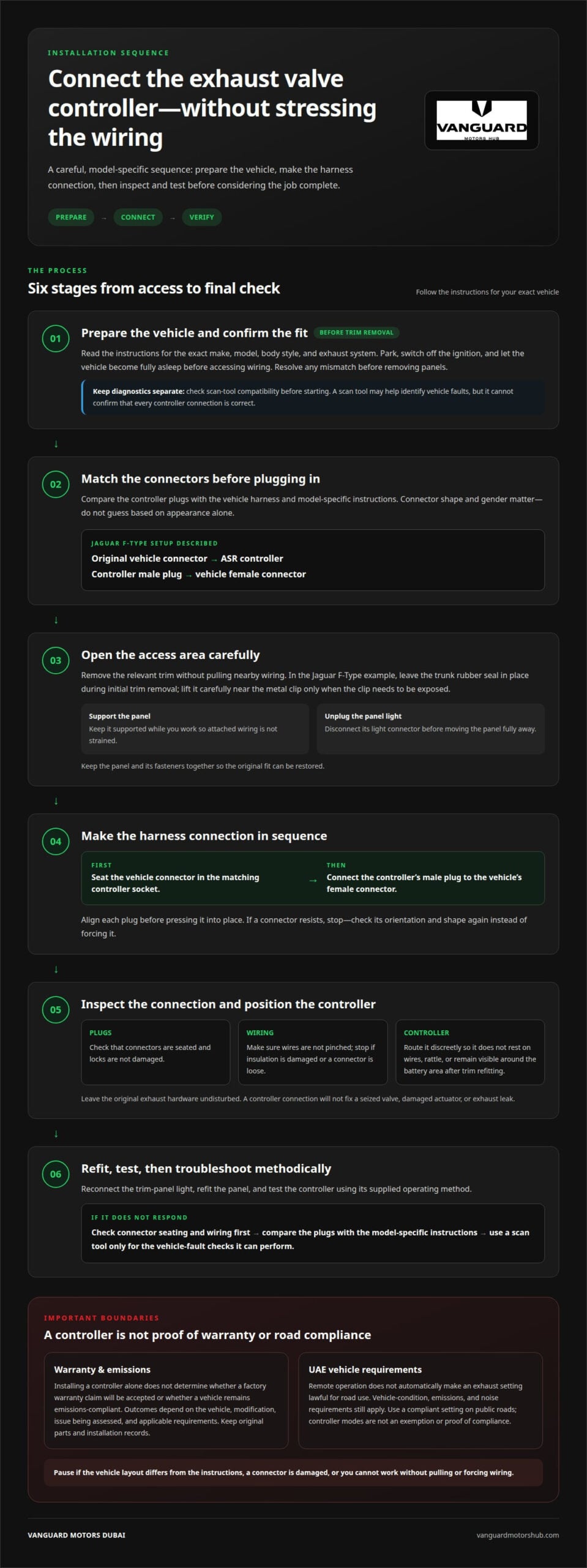
- Identify the matching connectors. Before connecting anything, compare the controller plugs with the vehicle harness and the instructions for your exact model. Connector shape and gender matter. In the Jaguar F-Type setup described here, the original vehicle connector plugs into the ASR controller, and the controller’s male plug connects to the vehicle’s female connector.
- Access the harness without stressing trim. Remove the relevant trim carefully to reach the connector without pulling nearby wiring. In the Jaguar F-Type example, leave the trunk rubber seal in place during initial trim removal. Lift it carefully near the metal clip only when you need to expose the clip.
- Disconnect the trim-panel light before removing the panel. Support the panel as you work, then locate and unplug its light connector before moving the panel fully away. This prevents strain on the light wiring. Keep the panel and its fasteners together so you can restore the original fit after making the connection.
- Make the harness connection in sequence. Seat the vehicle connector in the matching controller socket, then connect the controller’s male plug to the vehicle’s female connector, as described for the Jaguar F-Type. Align each plug before pressing it into place. If a connector resists, don’t force it. Check its orientation and shape again.
- Understand the warranty and emissions implications. Installing a controller alone does not determine whether a factory warranty claim will be accepted or whether the vehicle remains emissions-compliant. The outcome depends on the vehicle, the modification, the issue being assessed, and applicable requirements. Keep the original parts and installation records, and don’t assume valve control changes emissions performance.
- Account for UAE noise and vehicle requirements. Remote operation does not automatically make an exhaust setting lawful for road use. UAE requirements for vehicle condition, emissions, or noise still apply. Use a compliant setting on public roads, and don’t treat a controller or its operating modes as an exemption or proof of compliance.
- Inspect for installation risks before refitting trim. Misaligned plugs or forceful handling can damage connector locks or wiring. A controller connection won’t fix a seized valve, damaged actuator, or exhaust leak. Check that plugs are seated, wires aren’t pinched, and the original exhaust hardware remains undisturbed. Stop if you find damaged insulation or a loose connector.
- Test and troubleshoot methodically. Reconnect the trim-panel light, refit the panel, and test the controller using its supplied operating method. If it doesn’t respond, first check connector seating and wiring, then compare the plugs with the model-specific instructions. A scan tool may help identify vehicle faults, but it can’t confirm that every controller connection is correct.
Preparing the car before installation
- Read the instructions for your exact vehicle. Match the controller documentation to the car’s make, model, body style, and exhaust system. For example, a Jaguar F-Type convertible may have different trim-access instructions from another body style. Resolve any mismatch before removing panels or handling connectors.
- Let the vehicle become fully asleep. The ASR controller instructions advise ensuring the car is fully asleep before installation. Park it, switch off the ignition, and let its systems settle before accessing the wiring area. Don’t begin while displays, lamps, or other vehicle systems remain active.
- Choose a stable, well-lit work area. Park on level ground, away from moving traffic and avoidable distractions. Good lighting helps you distinguish connector shapes, trim edges, and fasteners around the access area. Keep the work area clear so removed components won’t be stepped on or misplaced.
- Gather the correct tools and organize small parts. Use the tools specified by the controller’s vehicle-specific instructions rather than forcing trim with an unsuitable tool. Set aside a clean container for fasteners, and keep a light source nearby. Organizing these items first reduces interruptions once the panel is open.
- Inspect the access area before opening it. Look for loose trim, exposed wiring, signs of previous work, or damage near the intended connection point. Photographing the untouched area can help you remember the original wire routing and panel alignment. Stop if the harness or connector appears damaged.
- Plan the sequence before removing components. Identify which trim pieces block access, where each fastener belongs, and how wiring connects to the panel. A panel-mounted light, for example, may have its own lead. Account for attached components before moving a panel away from the vehicle.
- Keep the vehicle’s original setup clear in your notes. Record the intended controller connection points and the original position of accessible wiring. Don’t cut, splice, or reroute factory wires as a shortcut unless the exact installation instructions require it. Preserving the original harness keeps the work controlled and traceable.
- Pause if the vehicle’s layout differs from the instructions. Model-year, body-style, or prior modification differences can change access and connector details. Don’t guess at a plug or pull a panel that feels secured. If electrical access is unfamiliar, arrange professional automotive assistance before proceeding.
Routing and positioning the controller
- Trace the route before placing the module. Follow the controller lead from its vehicle connector to the intended mounting area. In the Jaguar F-Type example, the ASR controller sits behind the trim around the battery area. Map the route first so the lead reaches without crossing unrelated wiring or obstructing trim refitting.
- Keep the controller off the wiring harness. Position the module on a stable surface rather than leaving it to rest on wires. The harness may shift when trim moves or the vehicle is serviced. In the Jaguar F-Type installation described, the installer positioned the ASR controller so it would not rest on wiring.
- Check for movement and rattling. Gently check whether the controller shifts or taps against nearby surfaces. The ASR module should remain settled in position, not loose in the battery-area space. Don’t wedge it tightly against another component. Reposition it if contact or movement creates noise.
- Keep the module concealed behind the trim. Arrange the controller so it won’t be visible around the battery area once the trim is installed. In the Jaguar F-Type example, the installer aimed to keep it out of sight without removing the trim. Preserve access for future inspection rather than burying it behind unrelated components.
- Lay the lead without pulling it tight. Connectors should meet naturally, without tension from the cable route. Follow existing harness paths where they provide a clear channel, and don’t trap the lead beneath a panel edge. If moving the trim pulls the cable, adjust the route before securing the module.
- Check the route against every trim edge. Hold each removed panel near its installed position and check where the lead passes. For example, the Jaguar F-Type trunk trim must fit back without pressing on the controller or its wiring. Reposition anything that catches, bulges, or prevents the panel from aligning naturally.
- Preserve the panel-light connection and service access. Keep the trim-panel light lead clear of the controller wiring. Leave the light connector accessible until the panel is ready to refit. Keeping the leads separate makes later removal easier and reduces the risk of pinching either one behind the trim.
- Test the final position before closing the area. Check that the module is stable, the cable has no visible pinch points, and the trim fits as it did before removal. The Jaguar F-Type ASR controller should sit discreetly and securely, without rattling. Correct the route before the panel hides the installation.
Scan-tool compatibility
- Define the diagnostic task first. A scan tool may read fault codes, show live data, or support module functions, but capabilities vary. Before choosing equipment, identify the vehicle system and the check you need. A tool that retrieves engine codes may not access the module connected to exhaust-valve operation.
- Use the controller instructions to identify any required scan. Look for diagnostic, setup, or reset procedures for your specific vehicle. Don’t assume coding is necessary just because another model requires it. Scan-tool checks are only one part of an active exhaust valve controller installation, not a substitute for the controller’s physical connection instructions.
- Match the tool to the vehicle and module. A familiar diagnostic port doesn’t mean a scanner supports every system or function. Check its coverage for the vehicle’s make, model, and relevant control module. Compatibility depends on software access and supported functions, not just whether the connector fits.
- Distinguish fault reading from active control. A scanner that retrieves a stored fault may not command an exhaust valve or configure an added controller. Treat these as separate operations. Reading a code can reveal a reported issue, while commanding valve movement requires the appropriate supported function.
- Save existing fault information before work begins. If you have a suitable scanner, record pre-installation results before changing the vehicle. Note the affected system and displayed code description. This baseline can help you compare later warnings without assuming the controller caused a pre-existing fault.
- Interpret scan results within their limits. A clear screen doesn’t prove every connector is seated or that a valve moves correctly. A stored fault alone doesn’t identify the controller as its cause. Compare the displayed information with vehicle symptoms and the applicable diagnostic instructions.
- Choose a next step based on what the tool reports. If the scanner can’t access the relevant module, that alone doesn’t prove a wiring fault. If it displays a code, record it before clearing anything. Follow the vehicle-specific diagnostic process rather than repeatedly resetting warnings without addressing their cause.
- Keep diagnostic compatibility separate from installation compatibility. The vehicle configuration, controller, harness connection, and scan software each have distinct roles. For an active exhaust valve controller installation, follow the correct instructions for the physical work, then use diagnostic equipment only for functions it supports.
Can an active exhaust valve controller be installed at home, and what tools are needed?
- Decide whether the job matches your experience. A home installation may suit someone comfortable removing interior trim and handling vehicle connectors. The Jaguar F-Type example involves access around the trunk and battery area. If trim removal or electrical connectors are unfamiliar, stop rather than forcing parts or guessing at connections.
- Start with the vehicle-specific instructions. Keep the controller guide beside you and match it to the car’s model and body style. A Jaguar F-Type convertible guide, for example, may not describe trim access for another body style. Follow the exact sequence provided instead of relying on a general video or a similar vehicle.
- Prepare trim tools that suit the access point. A suitable trim-removal tool helps lift panels without pressing a screwdriver against visible surfaces. Keep a small tray for clips and fasteners, and use a work light to see connector locks. The required tool shapes depend on the panel and fasteners shown in the vehicle instructions.
- Keep the controller and connectors organized. Place the module, harness, and instructions on a clean surface before opening the vehicle. Don’t leave connectors where they can collect dirt or be stepped on. Keep removed fasteners separate from trim clips so each piece returns to its original position.
- Work only at the access point described. A plug-in harness connection doesn’t mean every panel needs to come off. In the Jaguar F-Type example, access involves trunk trim near the battery area. Avoid cutting factory wiring or adding tools to the circuit unless the controller’s model-specific instructions expressly require it.
- Keep basic checks within your skill level. Use a flashlight to inspect connector alignment and a phone camera to record the original routing before moving panels. Don’t probe vehicle wiring or use electrical test equipment unless you know the correct procedure. A scan tool is for separate diagnostic checks, not a substitute for correct harness connections.
- Set a clear point to stop. Pause if the connector shape differs, a panel resists removal, or wiring appears damaged. Resolve the specific issue rather than applying more force. A professional can handle the trim access and exhaust-system work if the installation exceeds your tools or experience.
- Choose the right route for the job. A straightforward connector-based setup can be manageable at home with matching instructions and careful trim handling. More complex exhaust work calls for suitable expertise and equipment. For guidance on a professional approach, discuss your exhaust installation needs.
Vanguard Motors Dubai: Paint Protection Film (PPF) Installation
Vanguard Motors Dubai installs Paint Protection Film (PPF) for drivers looking to protect their vehicle’s finish alongside mechanical upgrades. Once exhaust work is complete, PPF may be a useful next step for preserving the exterior. For a different look, Colored Sticker Wraps and Peelable Paint Applications offer additional finish options, while the Vanguard Premium Package suits a broader vehicle-enhancement project.
Choose the service that suits your vehicle’s condition and appearance goals. To discuss Paint Protection Film (PPF) Installation or another listed finish option, contact Vanguard Motors Dubai.
Plan Your Next Upgrade with Confidence
A considered active exhaust valve controller installation can be one part of a broader vision for your vehicle. Think about how you want its exterior to complement its driving character, then choose enhancements that support that direction. Give protection and appearance the same deliberate attention as mechanical details.
Vanguard Motors Dubai installs Paint Protection Film (PPF) to help protect your vehicle’s finish, as well as Colored Sticker Wraps and Peelable Paint Applications for a distinctive look. Choose the next step that fits your priorities, whether you want to preserve the existing finish or refresh its appearance.
For a direct conversation about your vehicle and these options, contact Vanguard Motors Dubai. Move forward with a clear goal and a finish that feels right for your car.
Frequently Asked Questions
What is an active exhaust valve controller and how does it work?
An active exhaust valve controller is an electronic module that changes how the exhaust valve operates. In a compatible setup, it interfaces with the vehicle’s valve-control circuit, allowing valve behaviour to be adjusted through the controller’s intended operating method. The exact interaction depends on the vehicle and controller design. It won’t repair a faulty actuator or exhaust component, so diagnose existing mechanical issues separately.
Where should the controller and wiring be mounted and connected?
Mount the module in a protected, secure area specified by the vehicle-specific instructions, away from exhaust heat, moisture, sharp edges, and moving parts. Connect only the matching harness plugs specified for that car, and keep wiring clear of hinges and panel edges. A route that looks tidy with the trim removed must still remain clear when the trim is closed and access panels move.
Which active exhaust valve controllers are compatible with different vehicle makes, models, and years?
Check compatibility against the controller instructions for the exact vehicle make, model, body style, and exhaust system. The ASR setup described here is for a Jaguar F-Type; the material provides no broader compatibility list.